Description
***** THIS IS A BESPOKE ITEM AND ARTWORK DRAWINGS WILL NEED APPROVAL BEFORE MANUFACTURE *****
The Series 6000SP range of Sprinkler/Life Safety Alarm Control Panels are designed to conform to BS EN 61010-1:2010 and are suitable for use on systems to comply with BS EN 12845 :2015
Available in a standard range from 8 to 88 monitored input ways each with internal power supply and space for Sealed Lead acid Batteries .
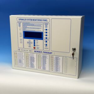
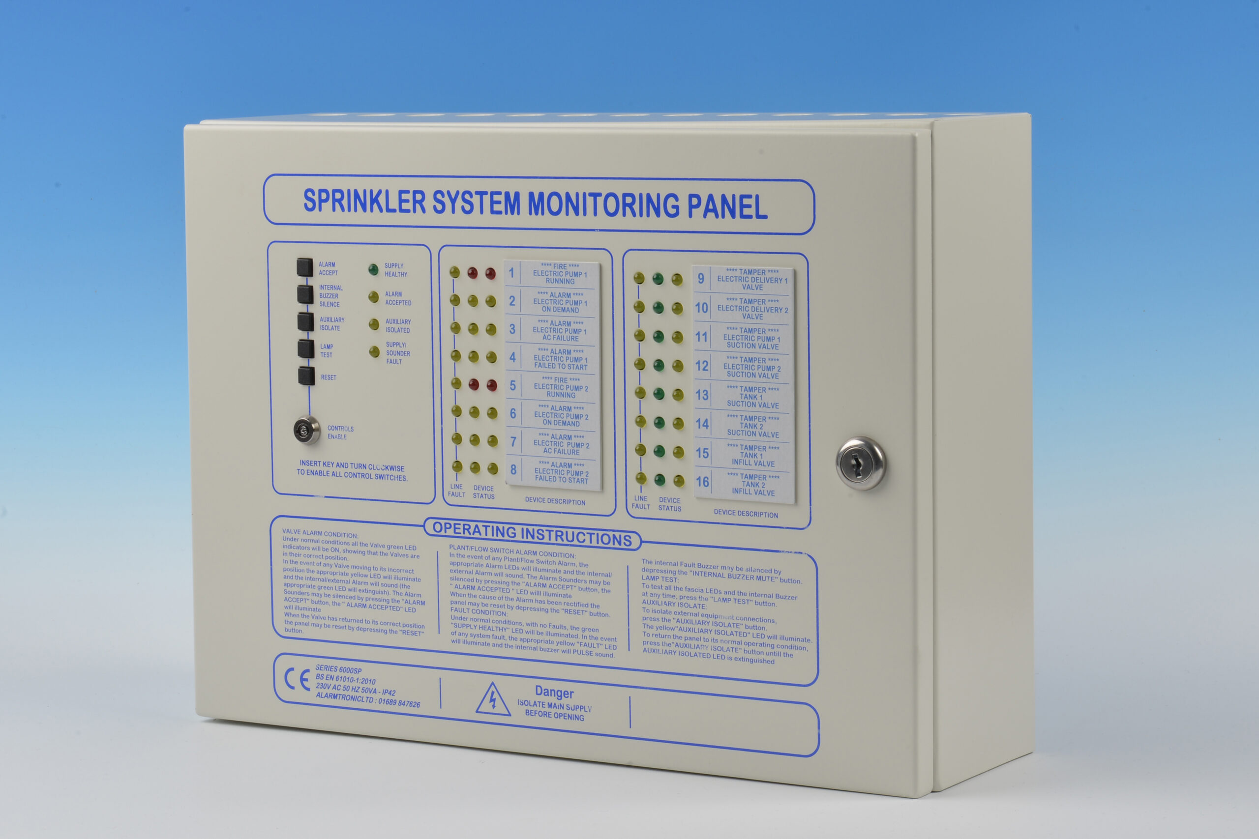
The panels are housed in an attractive metal enclosure with all user controls and indications located on the front fascia together with clear operating instructions . A bezel can be fitted to the back Box to enable the control panel to be flush mounted .
The Series 6000SP Sprinkler Alarm panels provide continuous monitoring of the Status of any Sprinkler Valve / Flow Switch or any other Plant alarm via a End of Line monitoring Resistor. Each input way can be set for either N/O or N/C switches via Internal Selector switches
Front panel Status LED’s for Valves being Green & Yellow ( for Normal/ Tamper) whilst for Flow/Pressure Switches Twin Red and for Plant Twin Yellow. Each input way is also provided with a Line Fault Yellow LED .
Any Alarm Way can be configured for either Valve Status or Flow/Pressure Switch or Plant alarm as per Clients specification . Location legends labels are provided and are removable.
An Layout drawing with Location Legends will be provided for approval before manufacture .
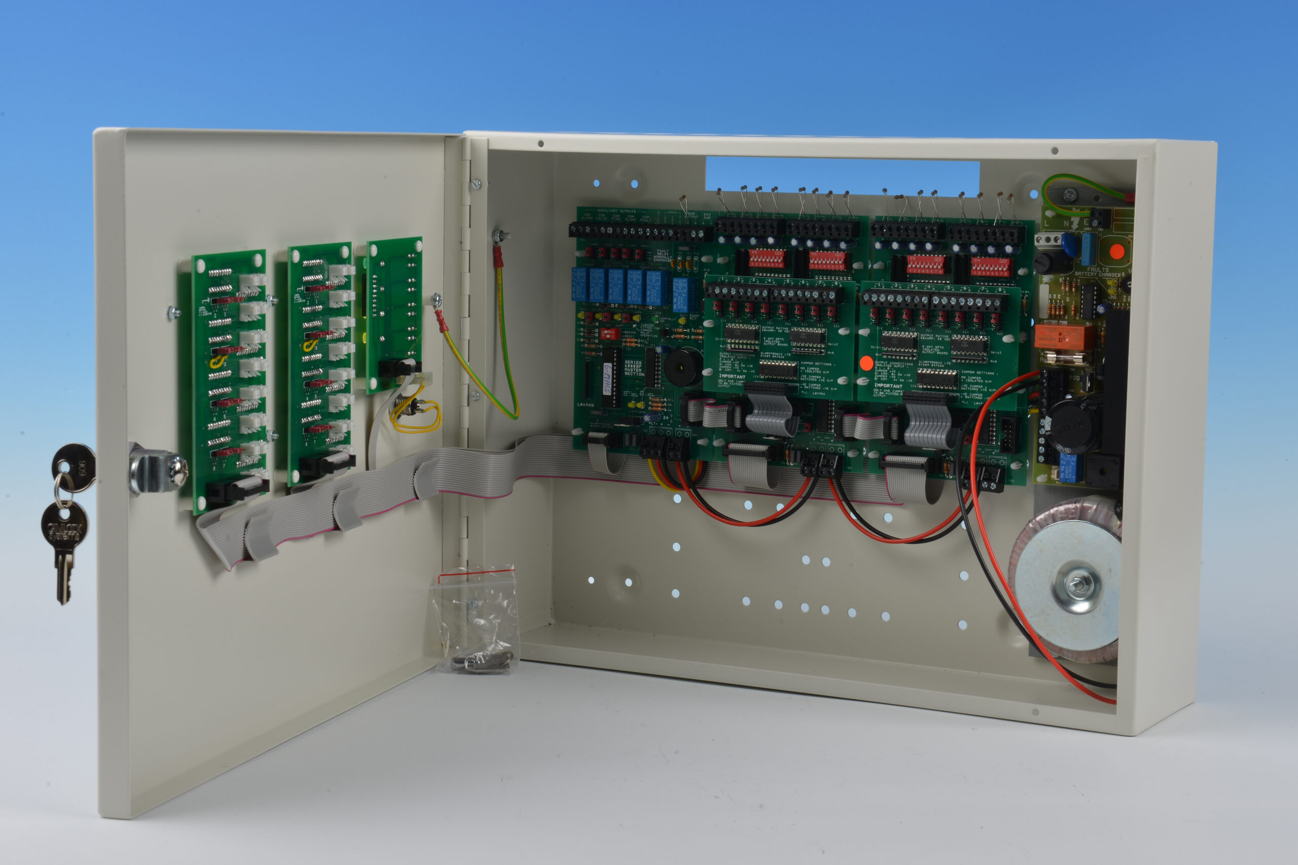
Auxiliary Contacts are provided for Common Alarm ( any Valve, Fire/Pressure or Plant), Common Valve Alarm ,Common Flow/Pressure Switch and Common Plant alarm . The operation of these output relays are configured via Jumpers located on the Input Motherboards. A Common System Fault auxiliary is also provided .
Each Auxiliary output can be configured for either N/O or N/C via jumper links. Opto-isolated outputs are also provided for each input way and be either configured for isolated , Switched +VE or Switched –VE via Jumper links.
Ample cable entries are located at the top of the Enclosure. On the Larger Panels removable internal chassis plates are provided.